Lecture 9: Double Patterning 👫
@luk036
2022-11-23
Background
-
In the past, chips have continued to get smaller and smaller, and therefore consume less and less power.
-
However, we are rapidly approaching the end of the road and optical lithography cannot take us to the next place we need to go.
Sub-wavelength Lithography
- Feature size << lithography wavelength
- 45 nm vs. 193 nm
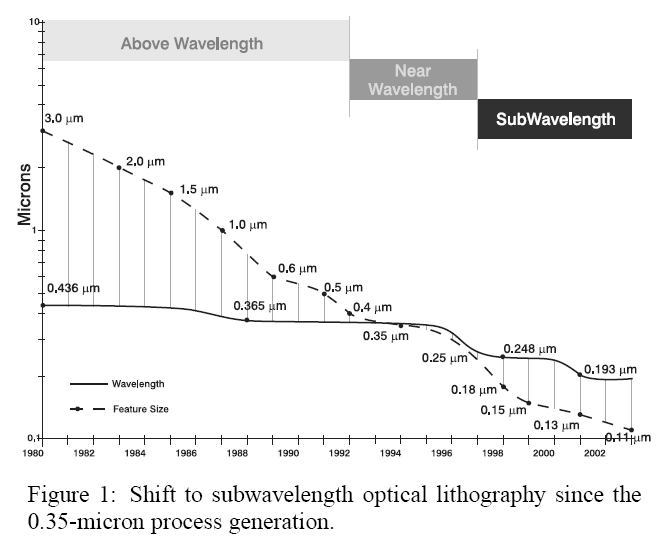
- What you see in the mask/layout is not what you get on the chip:
- Features are distorted
- Yields are declined
What is Double Patterning?

Unlike conventional optical lithography, which exposes the photoresist once under one mask, masks is exposed twice by splitting them into two, each with half its feature density.
Key technologies
-
Layout fracturing algorithm to reduce the number of rectangles and the total cut length.
-
Dynamic priority search tree for plane sweeping.
-
Graph-theoretic approach:
- Convert the coloring problem to a T-join problem and then solve it with Hadlock's algorithm.
-
Decompose the underlying conflict graph into its tri-connected components using a data structure named SPQR-tree.
Polygon Fracturing Algorithm
- Allow minimal overlap to reduce the number of rectangles, and thus the number of conflicts.

Conflict Detection
-
Rule 1: If the distance between two rectangles is , then the two rectangles are not in conflict.
-
Rule 2: Two overlapping/contacting rectangles are NOT conflict.
-
Rule 3:
-
Definition: A polygon is said to be rectilinearly convex if it is both x-monotone and y-monotone.
-
Two rectangles and are in conflict if they are apart and there is a path from to that reconstructs a "concave" polygon.
-
Conflicting: , , but not , and .
-

Conflict Graph

- Blue edge: positive weight (opposite color preferred)
- Green edge: negative weight (same color preferred)
Formulation of the Layout Decomposition Problem
- INSTANCE: Graph and weight function
- SOLUTION: Disjoint subsets of vertices and so that and .
- MINIMIZE: total cost where or
👉 Note: the problem is
- Linear time solvable for bipartite graphs.
- Polynomial time solvable for planar graphs.
- But in general, NP-hard (even for tripartite graphs)
Graph-Theoretic Approach
-
Q: How can we produce a high-quality result when the problem is NP-hard?
-
A: Observe that is a nearly planar graph: we can use Hadlock's algorithm.
-
However, the time complexity of this method is still very high.
-
Solution: Graph division methods.
SPQR-Tree
Connected Graph
-
Recall that a graph is a connected if every pair of vertices in is connected by a path.
-
A graph can be divided into its connected components in linear time.
-
Clearly, the color assignment problem can be solved independently for each connected component without affecting any QoR.
Bi-connected Graph
-
A vertex is called a cut-vertex of a connected graph if removing it disconnects .
-
If no cut-vertex is found in , then the graph is called a bi-connected graph.
-
In the following example, , and are cut-vertices.

Bi-connected Components
-
A division of into its bi-connected components can be performed in linear time by using a simple depth-first search to identify cut-vertices.
-
It can be easily shown that the color assignment problem can be solved for each bi-connected component separately without affecting any QoR [@chiang_fast_2005]
-
Question: Is it possible to further decompose the graph?
Tri-connected Graph
-
If removing a pair of vertices will disconnect , the pair is called a separation pair of .
-
If no separation pair can be found in , then it is called a tri-connected graph.
-
In the following example, , , , and are separation pairs.

Tri-connected Graph Division

SPQR-tree

- A division of into its tri-connected components can be performed by identifying the separation pairs in linear time with the help of SPQR-tree [@gutwenger_linear_2001].
Skeleton
-
Each tree node of SPQR-tree is associated with a tri-connected component of called skeleton
-
A skeleton represents a contraction of based on a set of virtual edges.
-
A skeleton was classified into four types:
-
Series (S): the skeleton is a cycle graph.
-
Parallel (P): the skeleton contains only two vertices and , and parallel edges between and where .
-
Trivial (Q): the skeleton contains only two vertices and , and two parallel edges between and , one of which is virtual and the other is real.
-
Rigid (R): the skeleton is a tri-connected graph of a type other than the above.
-
Divide-and-Conquer Method
Divide-and-conquer method
Consists of three basic steps:
-
Divide a conflict graph into its tri-connected components.
-
Conquer each tri-connected component in a bottom-up manner.
-
Combine the solutions into a complete solution in a top-down manner.
We calculate two possible solutions for each component, namely of the same color and of the opposite color.

Bottom-up Conquering: S Type

P Type

R Type

Top-down Merging

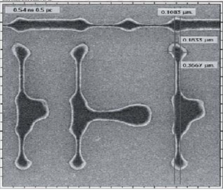
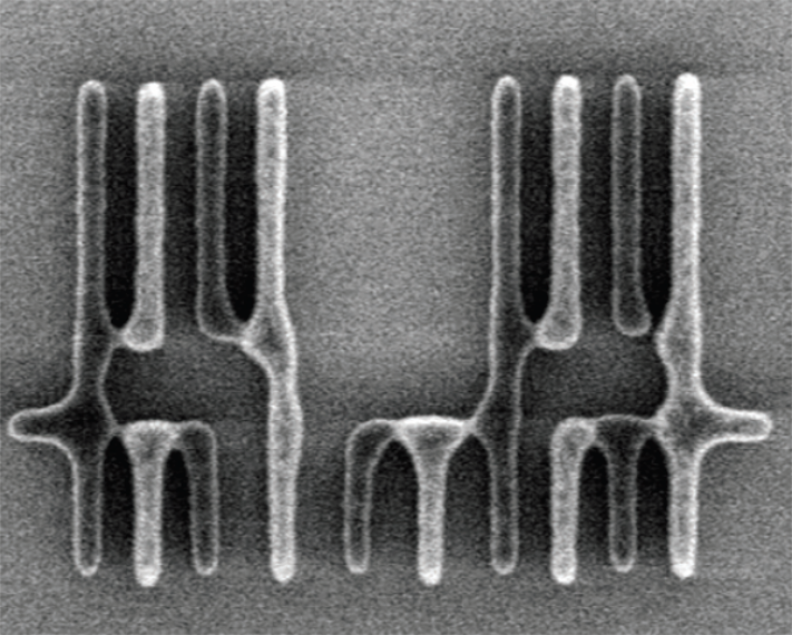
Node Splitting
- Node splitting (additional rectangle splitting) for resolving conflicts.
- To reduce the number of "cuts", we apply node splitting after one color assignment and then recolor.
.pull-left[
Before:

] .pull-right[
After:

]
class: middle, center
🧪 Experimental Results
45 nm SDFFRS_X2 Layer 11, 9


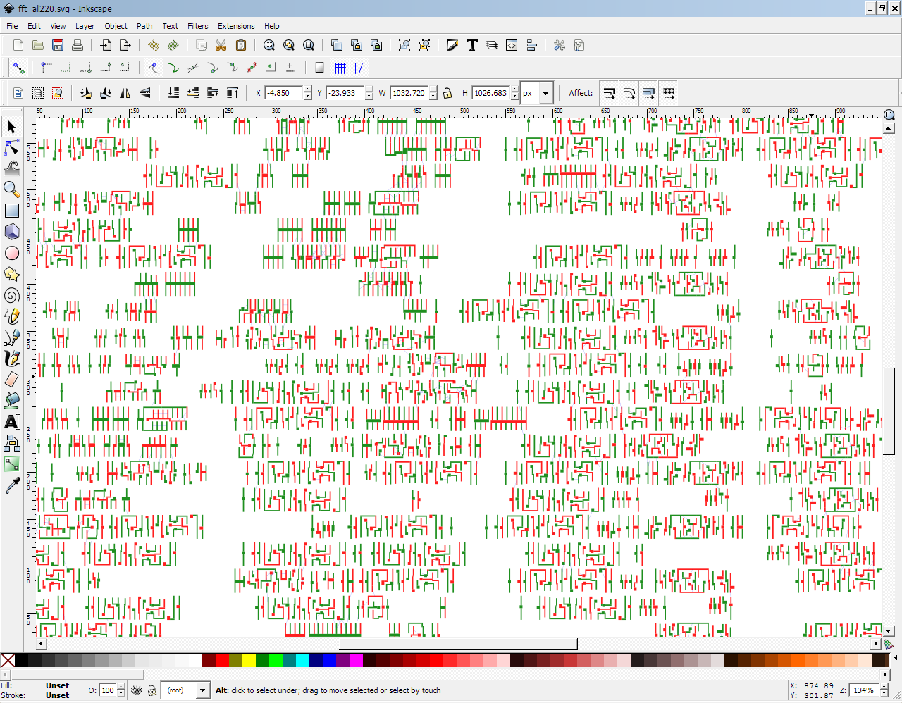 fft_all, 320K polygons
🧪 Experimental Results
| #poly | #nodes/#edges | w/ spqr | w/o spqr | time | cost |
|---|---|---|---|---|---|
| 3631 | 31371/52060 | 13.29 | 38.25 | 65.3% | 4.58% |
| 9628 | 83733/138738 | 199.94 | 2706.12 | 92.6% | 2.19% |
| 18360 | 159691/265370 | 400.43 | 4635.14 | 91.4% | 1.18% |
| 31261 | 284957/477273 | 1914.54 | 9964.18 | 80.7% | 1.61% |
| 49833 | 438868/738759 | 3397.26 | 15300.9 | 77.8% | 1.76% |
| 75620 | 627423/1057794 | 3686.07 | 17643.9 | 79.1% | 2.50% |
: Experimental results of the runtime and cost reduction (with minimizing the number of stitches)